Laboratory “Automation of technological processes, installations and complexes” 015-20
In the laboratory 015-20 “Automation of technological processes, installations and complexes” the educational process is carried out in the disciplines/credit modules “Synthesis of logical schemes”, “Automation systems-1” , “Automation systems-2” and “Automation systems-3. Course work”. The laboratory also allocates hours for independent work within the disciplines “Scientific research on the topic of a master’s thesis” and “Interdisciplinary research of electromechanical systems”.
There are 29 stands in laboratory 015-20. Among them: 12 static laboratory stands, 17 portable stands based on microcontrollers.
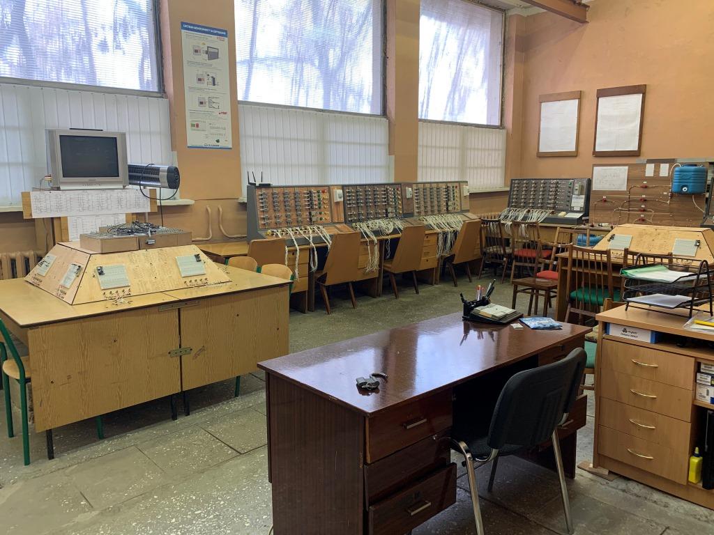
Figure 1 – General view of laboratory 015-20
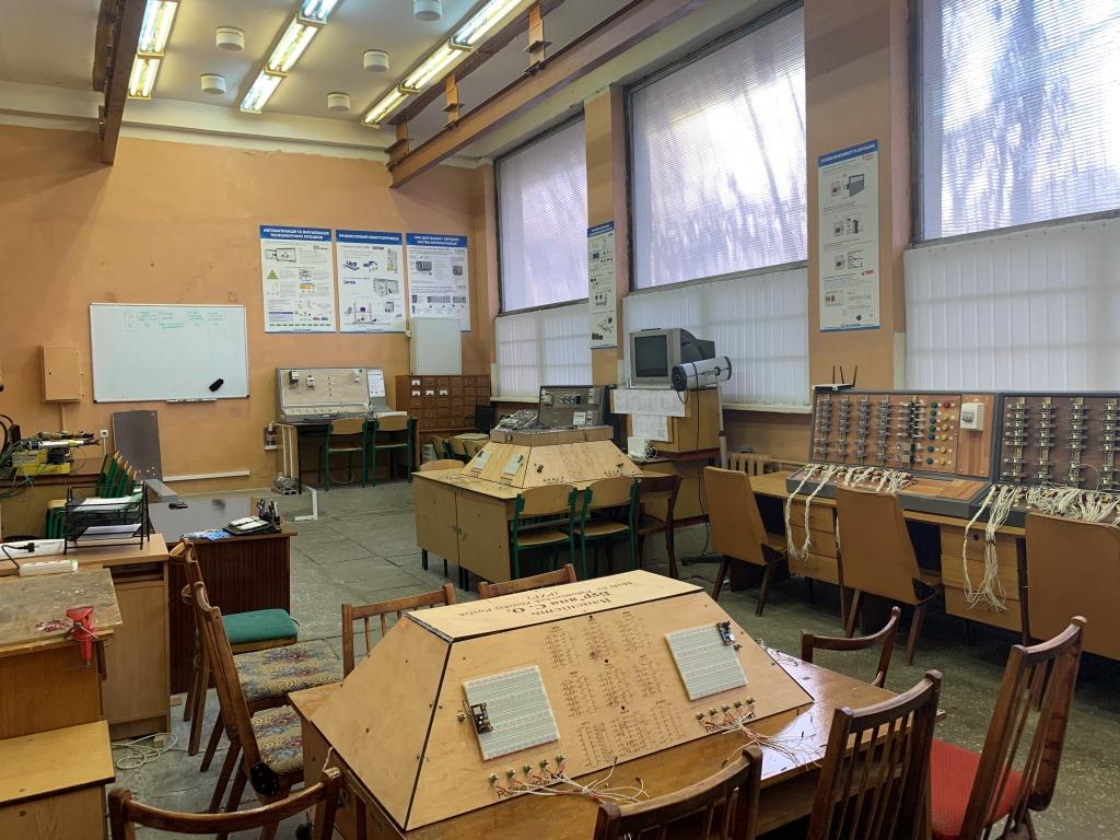
Figure 2 – General view of laboratory 015-20
- Discipline “Synthesis of logical schemes”.
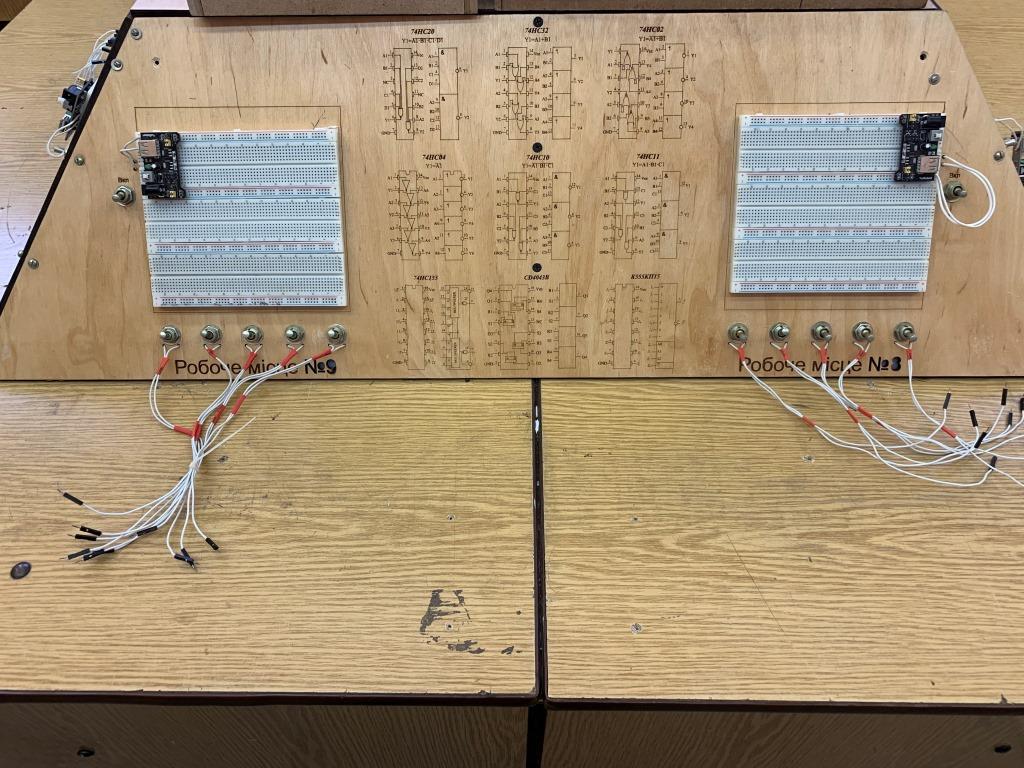
This discipline does not provide for laboratory work, but there is calculation and graphic work, in which there is a task to design an electrical principle diagram on integrated microcircuits. 2 laboratory stands “Logical synthesis and research of automation schemes on discrete logical elements” are used to check the efficiency of the completed tasks, which consist of circuit boards and sets of microcircuits, LEDs, resistors, etc. Students have the opportunity to assemble their schemes and visually check their efficiency.
The stand consists of a WB-101 mounting board, on which is powered by +5 V, as well as a set of logic chips (manufacturers of Philips, Hitachi, Texas Instruments, NXP Semiconductors, etc.), buttons, LEDs, conductors and resistors.
 |
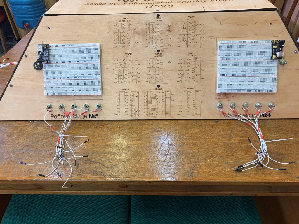 |
Figure 3 – Laboratory stands for testing RGR
Video guide to the implementation of the RGR
Video about the performance of laboratory and RGR by students
- Credit module “Automation systems-1”.
This credit module includes 18 hours of laboratory work, divided into 5 laboratory works.
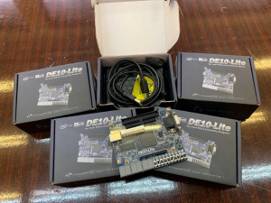
Labs 1-4 are performed on the basis of an FPGA-type developer board, DE10-Lite series. Each team receives a personal fee and works with its own tasks. A total of 7 boards of this series were received as part of the Altera University Program.
Figure 4 – DE10-Lite Developer Boards
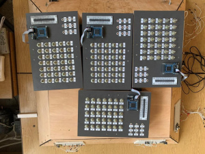
Laboratory work 5 is performed by each student individually. For this, 5 portable laboratory stands based on the Cyclone II FPGA controller have been developed. Each student receives 4 personal tasks, based on which he must make a synthesis, write a program, program a microcontroller and demonstrate the performance of the completed task.
Figure 5 – Stands for laboratory work 5 and checking coursework
List of laboratory works:
- DE10-Lite developer board I/O devices.
- Working with seven-segment indicators and timers.
- Synthesis and research of flip-flop circuits based on the DE10-Lite developer board.
- Investigation of pulse counters.
- Synthesis and research of automation systems of typical industrial mechanisms based on programmable logic integrated circuit (PLC).
- Credit module “Automation systems-2”.
This credit module includes 36 hours of laboratory work, which is divided into 8 laboratory works.
All laboratory work concerns the peculiarities of programming programmable logic relays and their interaction with various executive devices and work with relay-contactor equipment.
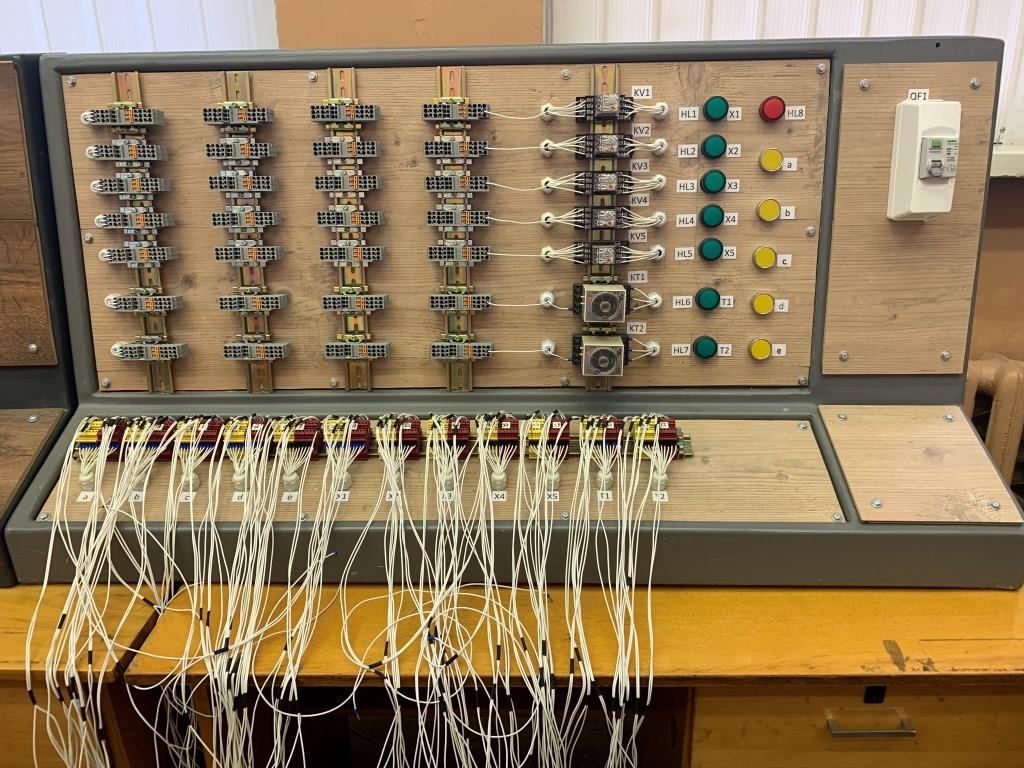
Laboratory work 6 “Investigation of relay-contactor schemes of automation” is performed by each student personally on a separate laboratory stand (a total of 4 such stands are mounted), which consists of a certain number of relays, including time relays, with three pairs of contacts. One pair of contacts is connected to an LED indicator to simulate the output singals. The students’ task is to perform a logical synthesis, build a relay-contactor circuit according to the obtained equations and check their performance on the stand.
 |
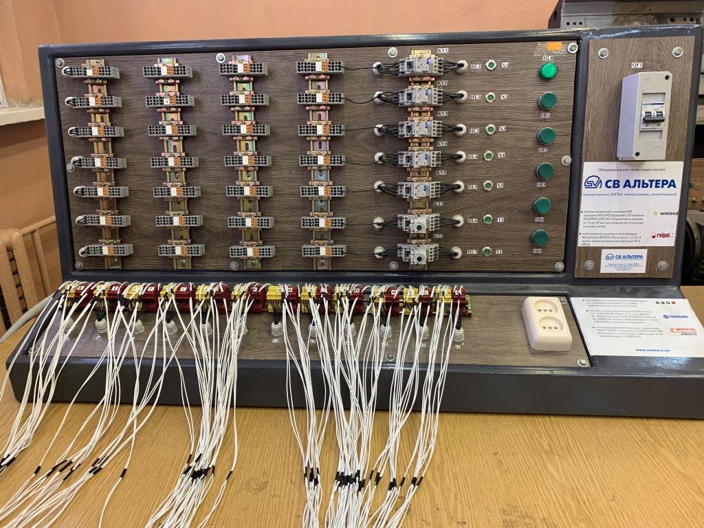 |
Figure 6 – Stands for laboratory work 6
Lab work 7 “Solution of automation problems based on the programmable controller Lovato” performed by the brigade. The peculiarity of this work is that contactors are connected to the outputs of the controller, which turn on and off three asynchronous motors. Thus, students perform various automation tasks on the sequence of turning on/off motors using timers, counters, etc.
 |
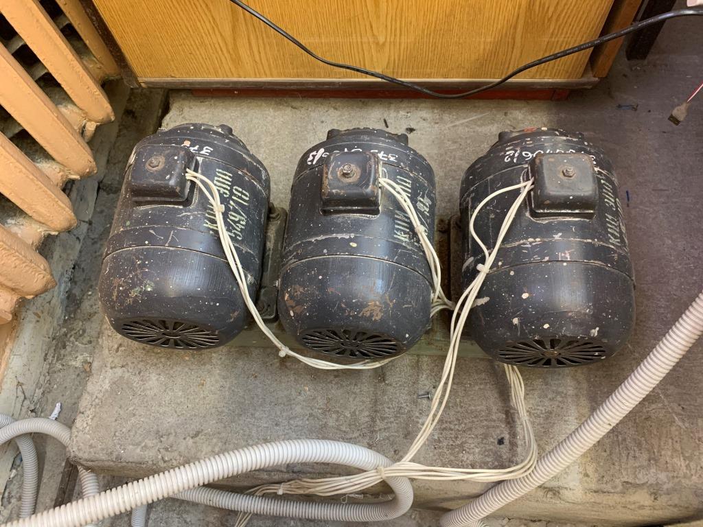 |
Figure 7 – Stand for laboratory work 7
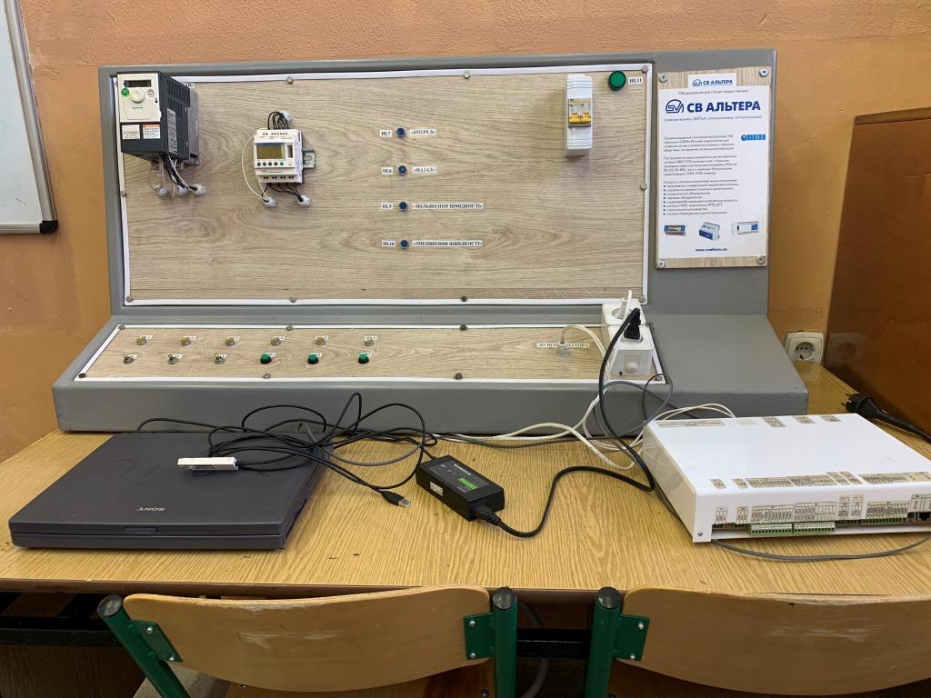
Laboratory work 8 “Investigation of systems for working out given trajectories based on the frequency converter Altivar and controller Zelio logic“ is performed by the team. The peculiarity of this work is that each team is given several set trajectories of engine operation at different speeds. Their task is to configure the converter to work with logic controllers, perform synthesis, write a program that will control the digital inputs of the converter in the “Digital Potentiometer” mode, and with the help of the “STEP-1” visualizer, which is connected to the tachogenerator armature, know the trajectory and make sure , which corresponds to the task.
 < /a> < /a> |
 < /a> < /a> |
Figure 8 – Stand for laboratory work 8
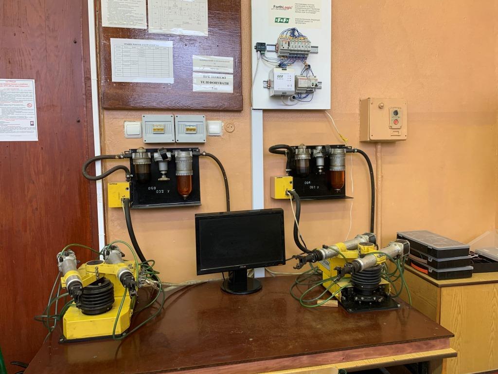
Laboratory work 9 “Research of the automation system based on the RF-202M industrial robot” is performed by the team. The peculiarity of this work is that students have the opportunity to work with a real SCADA system and an industrial pneumatic manipulator. The students’ task is to perform logical synthesis and write a JAVA Script program for the logic controller based on the given sequence of actions of the manipulators. After that, they must demonstrate the operation of the system for practicing the given movements in automatic mode.
Figure 9 – Stand for laboratory work 9
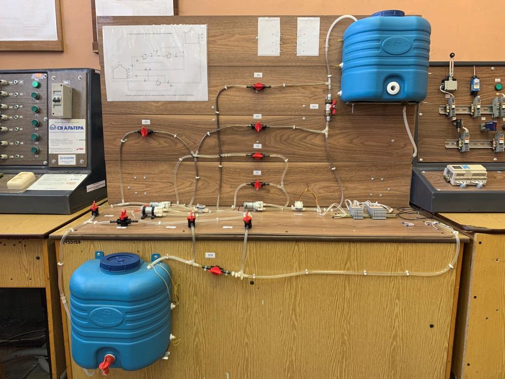
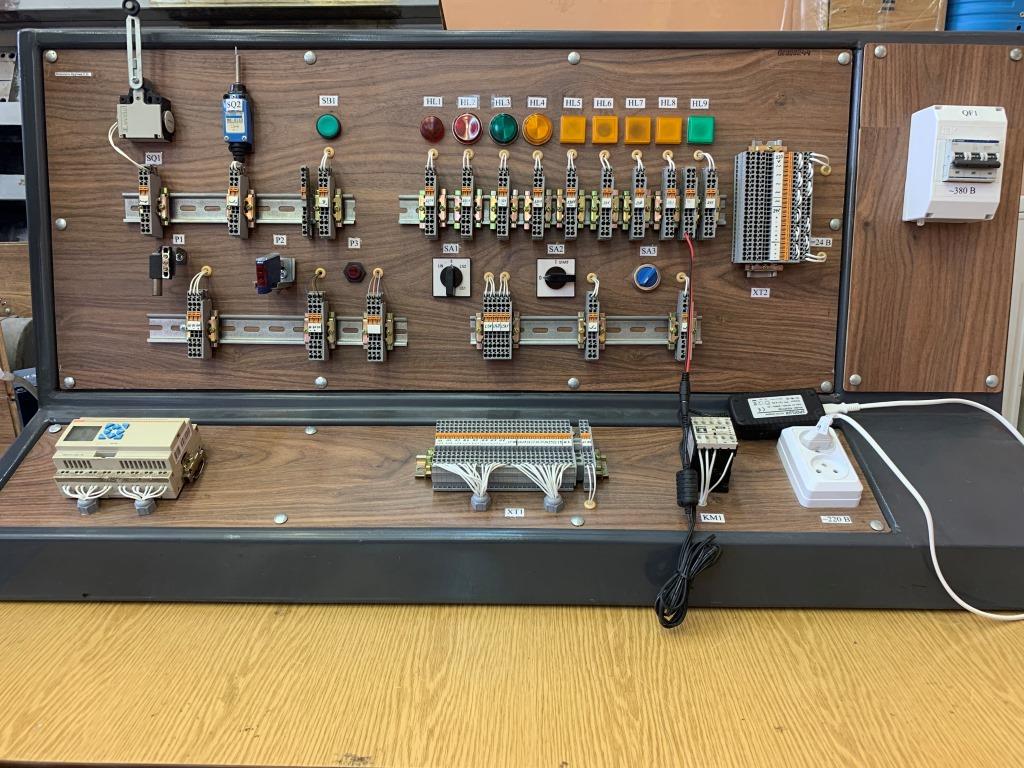
Laboratory work 10 “Investigation of the automation system of pumping installations” is performed by the team. The peculiarity of this work is that students are offered a hydraulic system with three micropumps, two tanks and discrete level transmitters in each of them. Each pump can work both for pumping and for pumping water from any tank, depending on the hydraulic circuit, which is completely adjusted manually with the help of 10 valves. Also, this is the only lab in which students independently connect all equipment to the logic controller, including power, input signals, pumps, etc. Before that, students independently choose the equipment they need, make a connection diagram, and after that they already make a physical connection.
 < /a> < /a> |
 < /a> < /a> |
Figure 10 – Stand for laboratory work 10
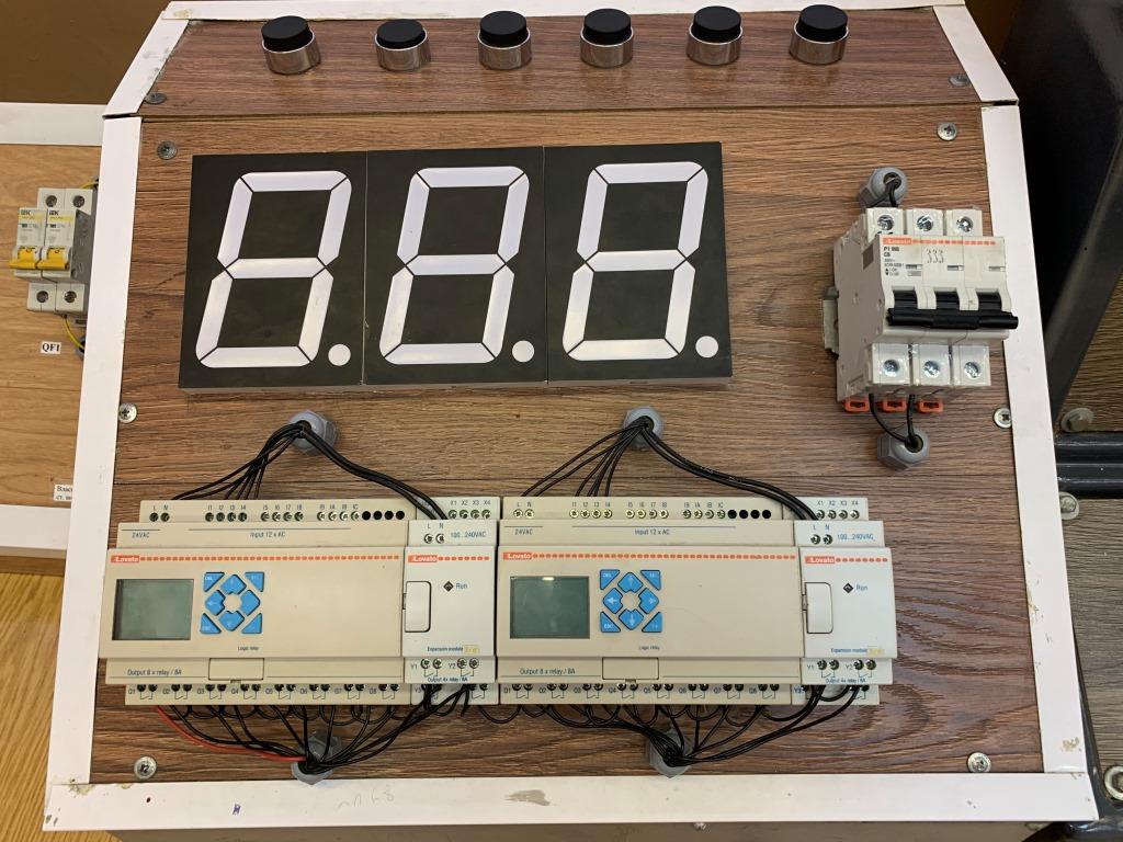
Lab 11 “Synthesis and research of number generators based on the programmable controller Lovato and seven-segment indicator” is performed by the brigade. The peculiarity of this work is that students are given several sequences of decimal numbers, which they must generate using a logic controller. The main goal of this work is to teach students how to program transition commands so that several modes can be used in one program.
Figure 11 – Stand for laboratory work 11
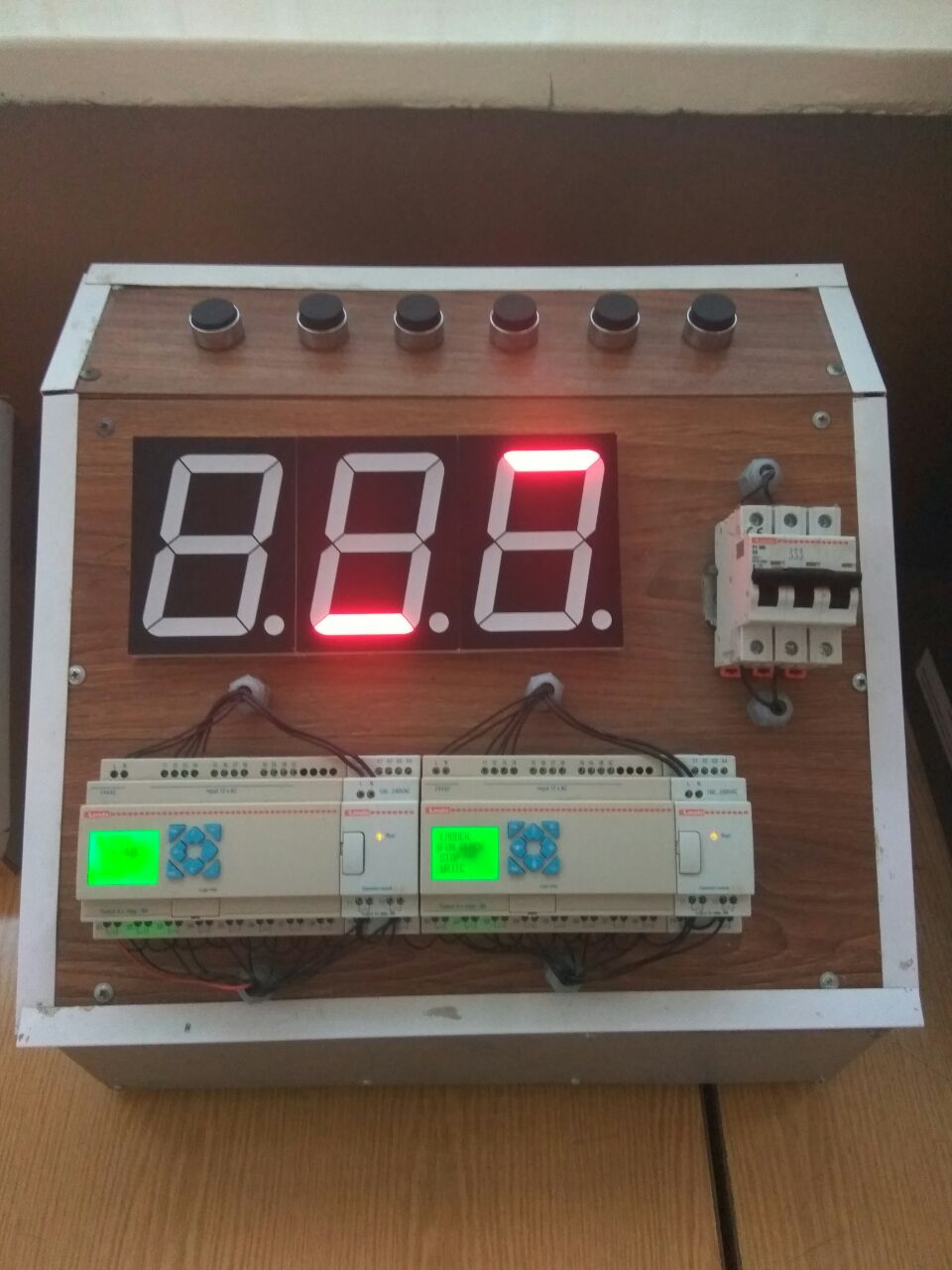
Lab 12 “Investigation of the cooperation of programmable logic controllers with expansion modules and LED indicators” </strong >performed by the brigade. The peculiarity of this work is that students must set up the joint operation of two controllers without using an electrical connection between them, but only with the use of timers.
Figure 12 – Stand for laboratory work 12
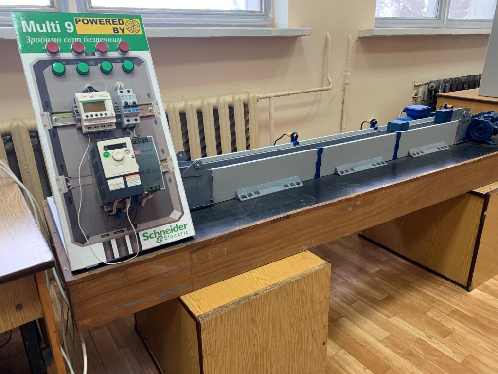
Laboratory work 13 “Investigation of the belt conveyor automation system” is performed by the team, and the stand itself is located in the adjacent laboratory 016-20 . The peculiarity of this work is that, under the given conditions, students perform the synthesis of the automation system of the flow-transport system using four sensors for the presence of objects on the conveyor belt.
 |
 |
Figure 13 – Stand for laboratory work 13
- Credit module “Automation systems-3. Course work”. In order to check the functionality of the developed automation system, the stand “Synthesis and research of automation systems of typical industrial mechanisms based on programmable logic integrated circuit (PLC)” is used, where students perform laboratory work 5. At this stand there are enough input/output signals to simulate the technological process specified in the course work. Students independently assign inputs/outputs of the microcontroller, connect input/output signals and check the performance of the developed control algorithms.
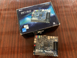
- Disciplines “Scientific research on the topic of the master’s thesis” and “Interdisciplinary research of electromechanical systems”. Within these disciplines, students are engaged in the development of control systems and artificial neural networks using more complex microcontrollers based on the FPGA-type developer board, DE1-SOC series. A total of 5 boards of this series were received as part of the Altera University Program.
Figure 14 – DE1-SOC Developer Board
